- 您现在的位置:买卖IC网 > Sheet目录484 > NOIV1SE025KA-GDC (ON Semiconductor)IC IMAGE SENSOR 25MP 355PGA
NOIV1SN025KA
Required Register Uploads
In this phase the ’reserved’ register settings are uploaded
through the SPI register. Different settings are not allowed
and may cause the sensor to malfunction. The required
uploads are listed in Table 9.
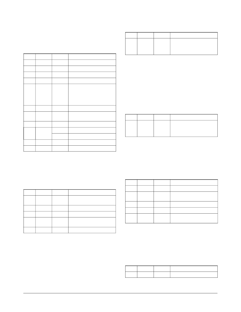
Table 9. REQUIRED REGISTER UPLOADS
Table 11. ENABLE SEQUENCER REGISTER
UPLOADS
No. Address Data Description
1 192[0] 0x1 Set ‘reg_seq_enable’ to ‘1’. All
other configuration bits of re-
gister 192 should remain
unchanged.
No.
Address
Data
Description
1
2
3
4
5
6
7
65
66
67
68
128
204
224
0x008B
0x53C6
0x0844
0x0086
0x4520
0x09E5
0x3E04
General Biasing
AFE Biasing
Mux Biasing
LVDS Biasing
Set desired output level to code
32 for 10-bit mode, code 8 for
8-bit mode.
Set number of samples for
black calibration to 2 5 .
Configure unity gain
Dummy rows upon integration
start
User Actions: Functional Mode to Power Down
Sequences
Disable Sequencer
During the ‘Disable Sequencer ’-action, the frame
grabbing sequencer is stopped. The sensor will stop
grabbing images and returns to the idle mode.
The ‘Disable Sequencer ’ action consists of a set op
register uploads. The required uploads are listed in Table 12.
Table 12. DISABLE SEQUENCER REGISTER
UPLOADS
No. Address Data Description
8
9
225
129[13]
0x6733
0x0
0x1
Configure internal latency
10-bit Mode
8-bit Mode
1
192[0]
0x0
Disable of Sequencer.
NOTE: This address contains
other configuration bits to se-
lect the operation mode.
10
11
447
448
0x0BF1
0x0BC3
Configure sequencer
Configure sequencer
Soft Power Down
During the soft power-down action, the internal blocks are
disabled and the sensor is put in standby state in order to
Soft Power Up
During the soft power-up action, the internal blocks are
enabled and prepared to start processing the image data
stream. This action exists of a set of SPI uploads. The soft
power-up uploads are listed in Table 10.
reduce the current dissipation. This action exists of a set of
register uploads. The soft power-down uploads are listed in
Table 13.
Table 13. SOFT POWER DOWN REGISTER UPLOADS
Table 10. SOFT POWER UP REGISTER UPLOADS
No.
1
Address
112
Data
0x0000
Description
Disable LVDS Transmitters
No.
1
2
3
4
Address
32
64
40
48
Data
0x2003
0x0001
0x0003
0x0001
Description
Enable Analog Clock Distribu-
tion
Enable Biasing Block
Enable Column Multiplexer
Enable Analog Front-End
(AFE)
2
3
4
5
48
40
64
32
0x0000
0x0000
0x0000
0x2002
Disable Analog Front-End
(AFE)
Disable Column Multiplexer
Disable Biasing Block
Disable Analog Clock Distribu-
tion
5
112
0x0007
Enable LVDS Transmitters
Disable Clock Management
The ‘Disable Clock Management’-action stops the
Enable Sequencer
During the ‘Enable Sequencer ’-action, the frame
grabbing sequencer is enabled. The sensor will start
grabbing images in the configured operation mode. Refer to
Operating Modes on page 11 for an overview of the possible
operation modes.
internal clocking in order to further decrease the power
dissipation. This action exists of a set of register uploads as
listed in Table 14.
Table 14. DISABLE CLOCK MANAGEMENT
UPLOADS
The ‘Enable Sequencer’ action consists of a set op register
uploads. The required uploads are listed in Table 11.
No.
1
Address
34
Data
0x0000
Description
Disable Logic Blocks
http://onsemi.com
16
发布紧急采购,3分钟左右您将得到回复。
相关PDF资料
NP100P04PDG-E1-AY
MOSFET P-CH -40V MP-25ZP/TO-263
NP100P04PLG-E1-AY
MOSFET P-CH -40V MP-25ZP/TO-263
NP100P06PDG-E1-AY
MOSFET P-CH -60V MP-25ZP/TO-263
NP100P06PLG-E1-AY
MOSFET P-CH -60V MP-25ZP/TO-263
NP109N04PUJ-E1B-AY
MOSFET N-CH 40V MP-25ZP/TO-263
NP109N055PUJ-E1B-AY
MOSFET N-CH 55V MP-25ZP/TO-263
NP110N03PUG-E1-AY
MOSFET N-CH 30V MP-25ZP/TO-263
NP110N04PDG-E1-AY
MOSFET N-CH 40V MP-25ZP/TO-263
相关代理商/技术参数
NOIV1SE1300A-QDC
功能描述:图像传感器和彩色传感器 VITA 1300 1.3 Mpx 150FPS Globl Shutter RoHS:否 制造商:Avago Technologies 类型:Color Sensors 工作电源电压:2.5 V 封装 / 箱体: 图象大小: 颜色读出:Color 最大工作温度:+ 70 C 最小工作温度:- 25 C 封装:Reel
NOIV1SE1300A-QXC
制造商:ONSEMI 制造商全称:ON Semiconductor 功能描述:VITA 1300 1.3 Megapixel 150 FPS Global Shutter CMOS Image Sensor
NOIV1SE1300A-XDC
制造商:ONSEMI 制造商全称:ON Semiconductor 功能描述:VITA 1300 1.3 Megapixel 150 FPS Global Shutter CMOS Image Sensor
NOIV1SE1300A-XXC
制造商:ONSEMI 制造商全称:ON Semiconductor 功能描述:VITA 1300 1.3 Megapixel 150 FPS Global Shutter CMOS Image Sensor
NOIV1SE2000A-QDC
功能描述:IC IMAGE SENSOR 2.3MP 52LLC RoHS:是 类别:传感器,转换器 >> 图像,相机 系列:* 标准包装:480 系列:- 象素大小:6.7µm x 6.7µm 有源象素阵列:768H x 488V 每秒帧数:52 电源电压:3.3V 类型:CMOS 成像 封装/外壳:48-QFP 供应商设备封装:48-QFP 包装:托盘 请注意:* 配用:4H2105-ND - HEADBOARD FOR KAC-004014H2104-ND - KIT EVAL FOR KAC-00401 其它名称:4H20954H2095-NDKAC-00401-CBC-LB-A0
NOIV1SE5000A
制造商:ONSEMI 制造商全称:ON Semiconductor 功能描述:VITA 5000 5.3 Megapixel 75 FPS Global Shutter CMOS Image Sensor
NOIV1SE5000A-QDC
功能描述:图像传感器和彩色传感器 VITA 5000 5.3 Mpx 75FPS Global Shutter RoHS:否 制造商:Avago Technologies 类型:Color Sensors 工作电源电压:2.5 V 封装 / 箱体: 图象大小: 颜色读出:Color 最大工作温度:+ 70 C 最小工作温度:- 25 C 封装:Reel
NOIV1SN025KA-GDC
功能描述:IC IMAGE SENSOR 25MP 355PGA RoHS:是 类别:传感器,转换器 >> 图像,相机 系列:* 标准包装:480 系列:- 象素大小:6.7µm x 6.7µm 有源象素阵列:768H x 488V 每秒帧数:52 电源电压:3.3V 类型:CMOS 成像 封装/外壳:48-QFP 供应商设备封装:48-QFP 包装:托盘 请注意:* 配用:4H2105-ND - HEADBOARD FOR KAC-004014H2104-ND - KIT EVAL FOR KAC-00401 其它名称:4H20954H2095-NDKAC-00401-CBC-LB-A0
